Vectorworks Fundamentals and all Vectorworks Design Series products include a limited door object containing parameters similar to those described here. In Vectorworks Fundamentals, the door object is inserted through the Resource Browser. In the Vectorworks Design Series products, the door object is inserted with the Door tool.
The Vectorworks Design Series includes door symbols in standard sizes and various configurations, ready to install in walls. Vectorworks Architect and Landmark provide extensive libraries of door symbols, listed by configuration and size.
Door objects can be saved as editable red symbols that become plug-in objects when inserted into a wall (see Creating a Window or Door Symbol). The door options can be customized in the Object Info palette. Customized doors can then be made into symbols and used in the file without having to reset the parameters. See Accessing Existing Resources
|
|
|
1.
|
Select the Door tool from the Building Shell tool set.
|
If this is the first time a door is placed on the drawing, the Door Settings dialog box opens. Otherwise, click Preferences from the Tool bar. Specify the default preferences, which apply to all doors placed subsequently in this file.
|
3.
|
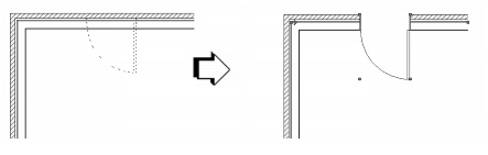
Specify the door parameters on each tab to define the door. As the parameters are defined, the preview dynamically displays the door appearance.
|
|
Use Symbol Geometry
|
Select Use Symbol Geometry and click Browse to select a door symbol from the current file’s resources. Select a symbol from the graphical list of Symbols and click OK.
The symbol Name displays in the Door Settings dialog box and the preview is updated with the selected symbol.
|
|
Enter the distance between the start of the top shape to the top of the door (not applicable for Square and Round Top Shape)
|
|
|
Enter the distance traveled above the floor before the Top Shape begins
|
|
|
Select the advanced operation for a sliding or complex swing door, where “O” represents a fixed door and “X” represents an operating door
|
|
Select to edit the settings for various door parts (jamb, leaf, lights, transom, trim, lintel, and threshold)
|
|
|
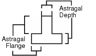
Use these two dimensions to determine the size of the astragal flange or depth (enter zero to display without an astragal flange); enabled if Swing Bi-part is selected in the Configuration field on the General tab
 |
|
|
|
|
|
For Custom Leaf Type, select the leaf type from the default resources; see Vectorworks Design Series Default Resources.
|
|
|
For Glass Leaf Type, select the muntin style
|
|
|
For Glass Leaf Type, enter the number of vertical/horizontal muntin bars
|
|
|
For Glass Leaf Type, enter the muntin bar width
|
|
|
For Panel Leaf Type, enter the number of vertical/horizontal panels in the door
|
|
|
For Panel Leaf Type, enter the width of any interim stiles
|
|
|
For Panel Leaf Type, select to set the top door panel at a different height than the other panels and specify the desired Panel Height
|
|
|
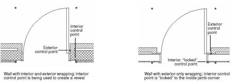
(1) Depth(Int) /
(2) Depth(Ext) |
|
|
6.
|
|
Select whether to draw wall lines at all times; wall lines are drawn in the Ceiling-main class to easily create reflected ceiling plans
|
|
|
Settings controlling 2D line styles and weights for the door part; if enabled, these settings override the line style and weight settings from the Attributes palette
|
|
|
Choose the line style and weight to use for the selected part (jamb, leaf, trim, swing, sash, glazing, astragal, or wall lines) or select Set Thickness to open the Set Thickness dialog box for creating a custom line thickness; see Pen Attributes
|
|
|
|
|
|
Select the style Class to assign to the selected Part (interior and exterior rail/stile, panel, jamb, trim, and sash; lintel, threshold, and side light glazing), or select None; see Using Style Classes.
|
|
Select whether to include this door’s information in the door schedule and also set the door ID label to visible
|
|
|
Assigns alphanumeric information before the numerical label value; adding prefix information is optional
|
|
|
Assigns a numerical value to the ID; this number increments automatically if the auto-increment option is chosen in the ID Settings dialog box
|
|
|
Enter the minimum ID label bubble size (this value represents the bubble size times the layer scale; the bubble shape is maintained relative to the text inside it for ID bubble uniformity throughout the drawing file)
|
|
|
Select the bubble line style and weight, or select Set Thickness to open the Set Thickness dialog box for creating a custom line thickness; see Pen Attributes
|
|
|
Select the leader line style and weight, or select Set Thickness to open the Set Thickness dialog box for creating a custom line thickness; see Pen Attributes
|
|
|
Select whether to use a marker for the ID leader line and choose the desired style from the marker list, or select Custom to create a custom marker. Select Edit Marker List to open the Edit Marker List dialog box; see Setting Default Marker Types.
|
|
|
Select the ID label class, or select None (which sets the ID to the same class as the door), the standard class for the ID, or any other class in the document
|
|
|
Select to include a door hardware set with the door object, and click Browse to open the Door Hardware Library dialog box; see Assigning, Creating, Editing, and Deleting Door Hardware Sets. The door hardware set selected in the Door Hardware Library box displays in the hardware Name field of the Door Settings dialog box.
|
|
|
Select the data field from the list and its Name displays beneath the list; select the user fields to include additional user-defined information with the door
|
|
|
Enter the data field Value for use in the door schedule
|
|
8.
|
Click OK to set the door parameters and close the Door Settings dialog box.
|
Door objects can also be edited in the Object Info palette. If the door has been inserted as a plug-in object, most settings from the Window Settings dialog box display. If the window is a black symbol made from a window object, fields pertaining to window geometry do not display.
Two additional Object Info palette parameters are available for windows inserted in a wall: click Flip to flip the window orientation, or click Position to open the Position Symbol in Wall dialog box to enter the distance from the symbol’s insertion point to the corner of the selected wall.
|
10.
|
The door schedule and/or door hardware legend can be added to the drawing from the VA Create Schedule command (see Creating Schedules) or the Resource Browser. From the Resource Browser, open the Libraries\Defaults\Reports~Schedules\Architectural Reports.vwx file that is included with Architect. Drag the door schedule or door hardware legend worksheet to the drawing. The worksheet is populated with information from the objects in the current drawing. To edit the worksheet after it has been created, see Using Worksheets.
|