There are several ways to modify sheet layer viewports; their appearance can be completely different from the original design layers, for presentation purposes.
A sheet layer viewport can be edited like most 2D objects. For information on 2D tools and commands, see Editing 2D Objects. 3D tools cannot be used on sheet layers. However, a 3D object can be copied from a design layer and pasted on a sheet layer. A design layer viewport (Design Series required) cannot be pasted on a sheet layer.
|
|
Use the Cut, Copy, and Paste commands to copy or paste a viewport on its original sheet layer or another sheet layer. Use the 2D Selection tool to drag a viewport to a new position (or edit the X- and Y-axis positions in the Object Info palette). Press the Delete key to delete a selected viewport.
|
|
|
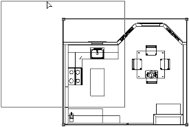
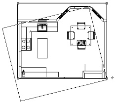
Use the Move, Rotate, and Mirror commands and the Rotate and Mirror tools to move, rotate, or mirror a viewport. The viewport can be split by the Split tool (in Split by Line mode), and clipped with the Clip tool.
|
|
|
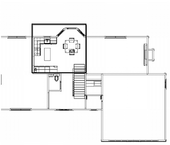
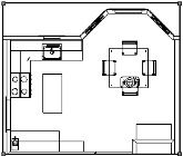
Use the Scale Objects command to scale a viewport. Any crop objects in the viewport are also scaled, as are annotations and dimensions. Viewport text, however, is not scaled unless Scale Text is selected in the Scale Objects dialog box.
|
|
|
|
|
Use the Eyedropper tool to transfer attributes from one viewport to another; see Transferring Attributes.
|
|
2.
|
Select Modify > Edit Viewport.
|
|
Display using Viewport Attributes
|
If the Navigate Back to Viewport option is also selected, the file’s layer and class visibilities return to their original status when you return to the viewport; otherwise, the file’s attributes remain the same as the viewport’s.
|
|
Add Reference Crop Object
|
When a viewport has been cropped, this option displays the crop on the design layer so that edits can be made to the design layer while knowing the position of the crop object.
|
|
Navigate Back to Viewport
|
Temporarily adds a Return to Viewport button to the design layer that returns you to the viewport when the edit to the design layer is complete (similar to an Edit Group operation).
To exit to the design layer instead of exiting to the viewport from design layer editing mode, press Shift + Esc. Alternatively, right-click (Windows) or Ctrl-click (Macintosh) in the drawing area, and select Exit Viewport from the context menu.
|
|
Display Viewport Cache
|
If the viewport is currently in a render mode other than Wireframe, select Display Viewport Cache to display a cache image of the rendered viewport during editing; deselect to display a Wireframe view of the viewport.
|
|
When you return to the viewport after an edit, this setting maintains any view changes (zoom and view location) made during edits to the viewport annotation or the crop object. Deselect this option to return to the original viewport view settings after editing.
|
|
|
Sets the future behavior when a viewport is double-clicked, eliminating the display of this dialog box if desired. If the Edits the Design Layer option is selected, a double-click activates the design layer of the double-clicked object. If the object does not belong to a design layer, the Edit Viewport dialog box opens to select a design layer to edit.
|
|
3.
|
Click Design Layer and select the design layer to edit from the list. Select Display using Viewport Attributes to view the design layer with the viewport attributes (orientation, projection, render mode, and layer and class visibilities). A rendered viewport displays the original design layer with the viewport’s render mode; however, the design layer’s render mode options for that mode are used. If the original design layer has different Z heights and Display using Viewport Attributes is selected, the layer options are set to Active Only.
|
Select Add Reference Crop Object to view the crop object on the design layer during editing. However, because the crop object is added to the design layer, it could become visible in other viewports that reference that area of the design layer.
Select Navigate Back to Viewport to easily return to the viewport when you are finished with the design layer edits. A colored border around the drawing window indicates that you are in an editing mode. The Return to Viewport button is visible in the top right corner of the drawing window.
To exit to the design layer instead of exiting to the viewport while in design layer editing mode, press Shift + Esc. Alternatively, right-click (Windows) or Ctrl-click (Macintosh) in the drawing area, and select Exit Viewport from the context menu.
|
4.
|
Click OK to make the selected design layer the active layer.
|
|
2.
|
Select Modify > Edit Viewport. The Edit Viewport dialog box opens (see Editing a Design Layer Displayed in a Sheet Layer Viewport for a description of the dialog box parameters).
|
|
3.
|
A colored border around the drawing window indicates that you are in an editing mode. The Exit Viewport Crop command becomes available from the Modify menu, and the Exit Viewport Crop button is visible in the top right corner of the drawing window.
|
4.
|
Create a 2D object (such as a rectangle, circle, oval, polyline, or polygon). The 2D object must define an area; for example, a 2D line cannot be used. Position the 2D object to delimit the new viewport display area. The fill of a viewport cropping object is always None; however, the pen style can be set from the Attributes palette while in Edit Crop mode. Set the pen style to None to make the crop object invisible.
|
To view other objects while in Edit Crop mode, select Show other objects while in editing modes on the Display tab of the Vectorworks preferences (see Display Preferences).
|
5.
|
Click Exit Viewport Crop to return to the sheet layer.
|
|
7.
|
To change, replace, or delete the crop object, select the viewport and then select Modify > Edit Viewport to re-enter Edit Crop mode. Alternatively, right-click (Windows) or Ctrl-click (Macintosh) and select Edit from the context menu.
|
Use the Edit Annotation mode to add annotations and dimensions in viewports, and to edit those annotations and dimensions later on.
|
1.
|
|
2.
|
Select Modify > Edit Viewport. The Edit Viewport dialog box opens (see Cropping Sheet Layer Viewports for a description of the dialog box parameters).
|
|
3.
|
A colored border around the drawing window indicates that you are in an editing mode. The Exit Viewport command becomes available from the Modify menu, and the Exit Viewport Annotation button is visible in the top right corner of the drawing window.
|
4.
|
Use the various dimension tools from the Dims/Notes tool set to add dimensions to the viewport (see Dimensioning). The dimension tools snap to the objects in the viewport as if you were dimensioning the design layer. When the viewport is in Top/Plan view, associative dimensions can be applied to 2D objects—including walls—on the design layer. The dimensions are automatically updated if the design layer object changes.
|
To view other objects on the sheet layer while in Edit Annotation mode, select Show other objects while in editing modes on the Display tab of the Vectorworks preferences (see Display Preferences).
Text, callouts, and other annotations, as well as 2D objects, can be added to the viewport. The Design Series contains additional annotation objects.
|
5.
|
Click Exit Viewport Annotation to exit Edit Annotation mode and return to the sheet layer.
|
|
6.
|
To change, replace, or delete the viewport annotations, select the viewport and then select Modify > Edit Viewport to re-enter Edit Annotation mode.
|
The viewport’s layer visibility, opacity, stacking order, and colors can be changed from the sheet layer. Other viewports, as well as the design layer properties, are not affected. The viewport attributes can be tailored as desired for presentation; several copies of the same viewport can appear completely different.
|
2.
|
|
Lists the viewport layers and their visibility, edited status, layer color use status, and stacking order. Click the triangle in the heading of an active column to toggle between ascending and descending sort order based on that column parameter.
|
|
|
Click to apply the viewport layer colors set in the Edit Viewport Design Layers dialog box (click Edit to set the colors, as described in the next step), overriding the design layer colors. This setting is independent of the Use layer colors document preference.
|
|
|
Displays the layer stacking order; drag a layer within the # column to change its stacking order. This column displays only when the viewport is in Top/Plan view.
|
|
|
Retain Design Layer Viewport Layer Overrides
|
If the sheet layer viewport contains a design layer viewport for which layer overrides have been set, this option uses the design layer viewport overrides, ignoring any layer overrides that may be set here for the sheet layer viewport
|
|
Indicates whether the layer stacking order in the viewport is different from the design layer stacking order. Click Revert Stacking Order to return to the original design layer stacking order. These fields display only when the viewport is in Top/Plan view.
|
|
|
4.
|
The same parameters apply when you create a design layer (see Setting Design Layer Properties); for viewport layers, only the stacking order, transfer mode or opacity, and colors can be edited. These edits apply to the current viewport only, though they can be transferred to other viewports with the Eyedropper tool.
|
The viewport layer colors can be controlled separately from the design layer colors, for flexible presentation output. Click Colors to override the fill and pen colors for the selected viewport layer. To see the effects of the color override, Use Layer Colors must be selected in the Viewport Layer Properties dialog box for the selected viewport. This is similar to the way that Use Layer Colors must be selected in Document Properties to see the layer color settings for a design layer, as described in Setting the Design Layer Color.
|
5.
|
Click OK to return to the Viewport Layer Properties dialog box.
|
Click Preview to evaluate the results of the property changes.
|
6.
|
Click OK to return to the sheet layer.
|
The class visibilities and attributes of a selected viewport can be changed from the sheet layer. This does not change the class properties or the class visibility for the original design layers or for other viewports. The viewport attributes can be tailored as desired for presentation; several copies of the same viewport can appear completely different.
|
2.
|
From the Object Info palette, click Classes.
|
The Viewport Class Properties dialog box opens. Change class visibilities and/or make class attribute overrides for the selected viewport.
|
Lists the viewport classes and their visibility and edited status; click in a class visibility column to change the class visibility for this viewport. Click the triangle in an active column to toggle between ascending and descending sort order based on that column parameter.
|
|
|
Retain Design Layer Viewport Class Overrides
|
If the sheet layer viewport contains a design layer viewport for which class overrides have been set, this option uses the design layer viewport overrides, ignoring any class overrides that may be set here for the sheet layer viewport
|
|
Opens the Edit Class(es) dialog box, to make overrides to the selected class that only apply to the current viewport (see Setting Class Properties)
|
|
|
Opens the Import Attributes dialog box, to import the class attribute settings from the file. The attributes can be imported for the classes selected in the Viewport Class Properties dialog box, from corresponding classes, or from a specified class in the file.
Click OK to import the class attributes into the selected viewport. (The Eyedropper tool can also transfer class override attributes between viewports.)
|
|
|
3.
|
Click OK to apply the class visibility and attribute changes to the selected viewport.
|